
The lever sets a speed only if nothing else changes
In an open-loop circuit the lever sets an opening, and the resulting speed depends on the load - the same relationship that makes a machine slow in hard ground. Travel is where this hurts most: on a downhill run the load starts to drive the motor, and the circuit is no longer controlling speed at all.
Hydraulic speed control systems exist precisely to close that gap. The usual arrangement adds local velocity feedback around the actuator: it raises stiffness and reduces the effect of changing valve parameters on the result. The course treatment adds the engineering caveat that matters when a machine is being set up: a speed loop is a zero-type system, which tends to have a high-frequency crossover and is therefore less comfortable for stability than a position loop. That is why speed loops are compensated rather than simply turned up.
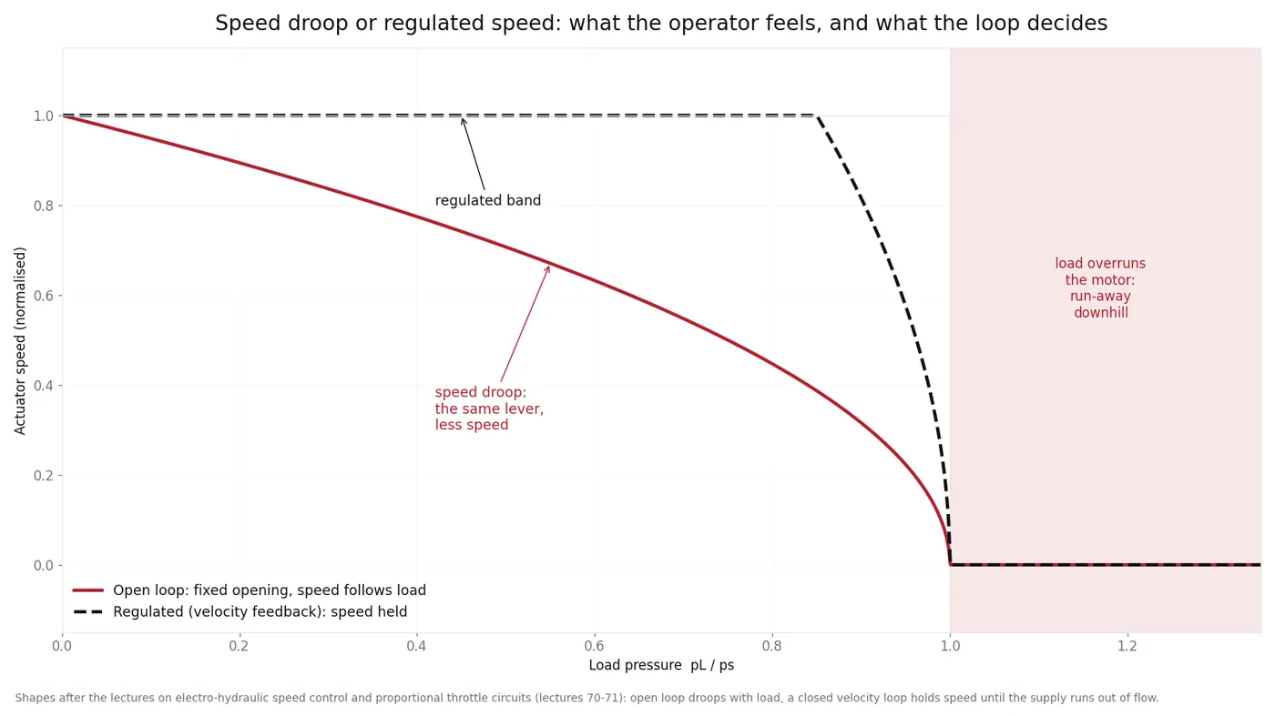
Why a machine runs away downhill
Three things normally stop it. The counterbalance valve (or brake valve) keeps a resisting pressure on the return side so the load cannot overrun the motor. The parking brake holds when the machine is stopped. The relief and replenishing circuit keeps the closed loop full of oil and prevents cavitation when the motor is being driven.
When an operator reports travel drift or run-away, check them in that order. A counterbalance valve with a wrong setting or a swollen O-ring, a brake that releases late, and a charge pump that cannot keep up all produce the same complaint from the seat, and all are cheaper than a travel motor.
Valve-controlled or pump-controlled
Small-power speed control is usually valve-controlled: a proportional valve meters flow to a motor. Large-power drives - travel and swing on an excavator, hydrostatic transmissions on industrial machines - are pump-controlled instead, because throttling high power generates heat instead of motion. In pump-controlled systems you meet two further configurations: a constant-pressure source, where speed is set by changing motor displacement, and a constant-flow source, where flow is fixed and motor displacement does the rest. Which one a machine uses explains why the same fault appears differently on different models.
The bench version of the same question
The standard laboratory exercise for proportional speed control is a proportional throttle circuit feeding a motor, with a pressure gauge and a manual throttle for trimming. Two lessons from it survive into the field: the characteristic you are looking for is command against speed, and a one-way throttle is directional, so a circuit connected the wrong way round loses control in one direction and looks like a valve fault.
Field checklist for drift and run-away
| Check | How | Reading that condemns it |
|---|---|---|
| Counterbalance setting | Gauge on both sides of the motor while travelling on a slope | Return pressure collapsing under an overhauling load |
| Brake release and timing | Release pressure and the delay after the lever moves | Slow release (drag and heat) or delayed application (creep) |
| Charge pressure | Gauge in the closed loop, hot, at working speed | Low pressure: cavitation noise and loss of control downhill |
| Velocity feedback sensor | Signal at the controller while speed changes | No signal or a noisy one: the loop cannot correct anything |
| Proportional valve current | Measured at the coil, commanded and actual | Actual current not following the command |
Two of these five checks are electrical, which surprises people. A speed loop is only as good as the feedback signal it compares against.
Related reading: closed-circuit hydrostatic drives, throttling or displacement control, and travel weak diagnosis.