
Two numbers describe how a valve behaves
When a spool opens, oil starts to move - but how much, and at what pressure, depends on two properties engineers measure on every valve:
- Flow gain - the change in flow for a small change in spool position at a fixed load pressure. It sets sensitivity: a high flow gain gives a fast, sharp response and makes fine control difficult; a low flow gain feels smooth but reacts late.
- Pressure gain - the change in load pressure for a very small change in spool position at a fixed flow. A high pressure gain holds a load stiffly and resists drift; it is also unforgiving, so contamination at the metering edge shows up as jerky movement.
The two are different slopes of the same pressure-flow characteristic, which is why machine tuning is always a compromise: crispness costs stability, stiffness costs sensitivity.
Reading the pressure-flow curve
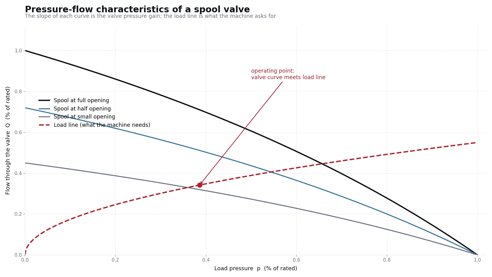
Three practical points follow from this picture:
- A larger opening is not simply "more speed". It moves the whole curve up, so the same load is met at a different flow - and every other function fed by that pump loses flow.
- The load line moves. Digging harder raises pressure and reduces flow, which is why a machine slows down in hard ground without anything being wrong with it.
- The space between the curves is heat. Flow that is generated but not used still leaves as temperature.
Matching the pump to the load
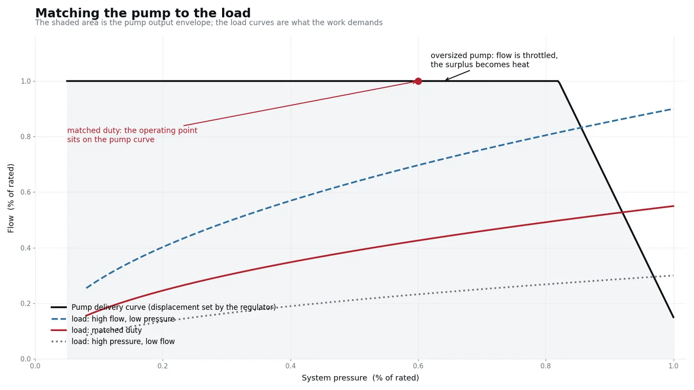
| How the machine is set up | What the operator feels | What happens in the oil |
|---|---|---|
| Pump matched | Full cycle speed at working pressure; the engine pulls steadily | Least throttling, lowest heat, longest component life |
| Pump oversized | Often no faster - the regulator or relief throttles the surplus away | Surplus flow becomes heat all shift; oil runs hot and seals age faster |
| Pump undersized | Slow cycle, higher working pressure, engine working harder than it needs to | Continuous operation close to the relief setting; the pump lives at its pressure limit |
This is why we will not "upsize" a pump on request without the machine details. Stepping from a 112 mL/r tandem to a 140 mL/r unit changes flow, input torque and regulator setting - and on a machine that was matched to begin with, the extra displacement usually ends up as heat rather than productivity.
What the regulator does with a mismatch
An excavator pump is not a fixed-displacement device. Its regulator continuously re-positions the swash plate so the torque taken from the engine stays inside the engine's capability, and so flow follows demand rather than running flat out. Two consequences matter in the field:
- Torque control protects the engine. If the regulator is out of adjustment or its spool sticks, the engine bogs down or smokes under load - the symptom appears at the engine, the cause is at the pump.
- Flow control protects the cycle. Negative-flow or positive-flow control reduces displacement as the control valve closes, which is what keeps idle-time heat down. A blocked control line or orifice leaves the pump working against a closed valve.
Field checks before ordering a pump
- Measure relief pressure and standby pressure first: both are quick, and both mimic a worn pump.
- Measure case drain flow at working temperature - that number separates wear from adjustment.
- Note when the machine is slow: always, only when hot, only under load, or only in one function. Each answer points somewhere different.
- Record the nameplate displacement and control suffix. Two units of the same displacement with different control codes are not interchangeable.
More detail in the field guides: engine bogging down under load, all functions slow, oil overheating and the case drain flow test.
Diagrams drawn by our own team; values are expressed as percentages of the rated point so that no specific machine setting is implied. Technical principles referenced from the public course “Hydraulic Servo and Proportional Control Systems” (Yanshan University).