
Two failures, one symptom
"It has no power" is the most expensive sentence in hydraulics, because a worn pump, a worn valve, a tired relief valve and an engine that cannot deliver torque all produce it. Replacing the most expensive component first is a guess, and the training material we work from makes the opposite point plainly: testing is the foundation, and a system that is measured is a system that can be improved.
The curve that describes a valve
A proportional or servo valve is specified by three groups of characteristics: static, dynamic and input. The static group contains the load flow characteristic, the no-load flow-pressure characteristic and internal leakage. Of the three, the load flow curve is the one to understand, because it is drawn dimensionless: load pressure over supply pressure on one axis, load flow over rated flow on the other.
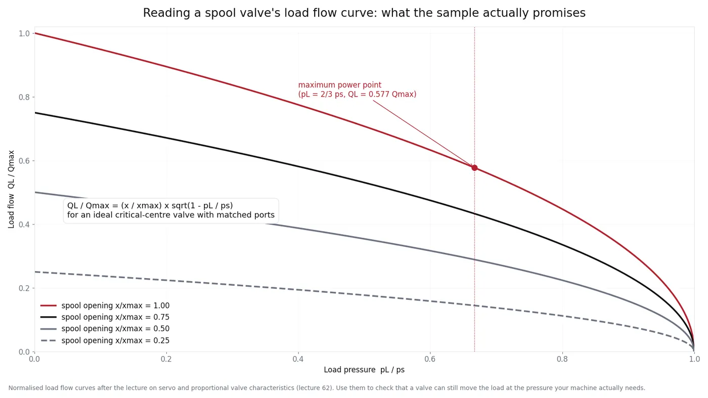
For an ideal critical-centre valve with matched ports and a constant supply pressure, the relationship is simple:
QL / Qmax = (x / xmax) × √(1 - pL / ps)
Two consequences follow, and both matter on site. The flow a function receives depends on the pressure it is working against, so a machine that slows down in hard ground is behaving correctly. And the maximum power the valve can transmit occurs when load pressure is about two thirds of supply pressure - which is why an oversized pump does not automatically make a machine stronger.
Why the test must be hot
Oil viscosity changes with temperature, and treating viscosity as a constant is one of the classic sources of error when simulation is compared with the machine. In practice, flow through a clearance rises quickly as oil warms and thins. A pump that looks acceptable when cold can be outside specification after two hours of work - and that is exactly the pump that gets condemned, or defended, in an argument.
The same caution applies to the assumption that pressure acts evenly on an area. It is a reasonable model, not a law, and it explains why measured pressure deviates from predicted pressure even when flow matches.
The measurement set that separates the two
| Measurement | How | Worn pump reads | Worn valve reads |
|---|---|---|---|
| Case drain flow | Hot, at working pressure, into a calibrated container for one minute | High and rising with pressure | Normal |
| Standby / cutoff pressure | Gauge on the pump outlet, all functions neutral | Low, or slow to reach setting | Normal |
| Flow at relief | Flow meter in the pressure line, function stalled against relief | Below rated delivery | Below rated delivery, but case drain is normal |
| Cycle time hot vs cold | Time one full boom cycle at the start of a shift and after two hours | Degrades with temperature | Degrades with temperature, but only on the affected function |
| Function-by-function check | Compare boom, arm, bucket, swing and travel | All functions affected together | One function or one direction affected |
The pattern is what you are reading, not any single number. Everything slow means upstream of the valve; one thing slow means at the valve, the cylinder or the pilot line.
Do not forget the transient
Steady-state readings miss the damage that happens at start-up. A pressure spike at the instant a machine starts can burst a hose or shock a pump, yet a gauge that reads a steady 32 MPa tells you nothing about it. If hoses keep failing in the same place, measure the transient: a peak-reading gauge or a data logger, and check the accumulator precharge and the response of the relief valve.
Working order
- Confirm the complaint and reproduce it: which function, hot or cold, loaded or empty.
- Set the machine to specification: relief, regulator, pilot pressure. Find the numbers before you measure anything.
- Take the baseline readings hot: case drain, standby pressure, cycle time.
- Isolate: cap a function, swap a line, or compare left and right where the machine has twins.
- Only then open a unit - and photograph the internals before cleaning them.
Send the readings and the nameplate photo and we will tell you which internal parts are likely: case drain high points at the rotating group, low standby pressure points at the regulator, and one slow function points at the valve rather than the pump.
Related reading: flow gain and load matching, the case drain test, and selection guides.