
Two ways to turn hydraulic pressure into rotation
A motor can be driven by a valve: a pump supplies a pressure line, a control valve meters oil to the motor, and speed follows the valve opening. Or it can be driven directly by the pump: the pump displacement alone sets the flow, and the motor follows. The second arrangement - a closed-circuit hydrostatic drive - is what excavator travel, swing and winch drives use, and the reason is efficiency.
In a valve-controlled drive the pressure drop across the metering edge is wasted as heat all day. In a closed circuit there is no metering edge in the main power path: what the pump displaces is what the motor receives, less leakage. That is why travel and swing can work a machine all shift without the oil temperature climbing the way it does when the same power is throttled through a valve.
What is actually inside a closed circuit
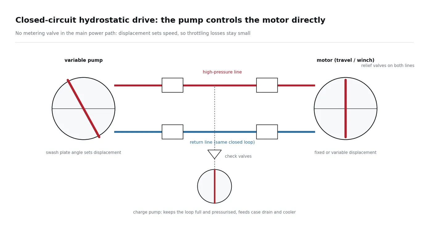
- Variable pump - displacement is set by the swash plate angle, so flow and speed are controlled without throttling. Reversing the swash plate angle reverses the motor.
- Motor - fixed displacement for a simple travel drive, variable displacement where the machine needs a wider speed range at constant power.
- Relief valves on both lines - either line can become the high-pressure side; both need protection against shock loads and stalled tracks.
- Charge pump - makes up the leakage that any closed loop has, keeps a minimum pressure on the low side so the motor cannot cavitate, and supplies oil to the case drain and cooler circuit.
- Case drain - the small flow that crosses the pistons, slippers and valve plate; measuring it is the standard way to judge wear on a motor or pump in a closed loop.
The behaviour, in two equations
The textbook treatment of a pump-controlled motor comes down to two statements that are worth knowing in plain language:
- Flow continuity: what the pump displaces equals motor displacement times speed, plus leakage, plus whatever is absorbed compressing the oil. Ignore the small terms and speed is set by the pump.
- Torque balance: motor displacement times the pressure difference equals inertia times acceleration, plus damping, plus the load. Pressure rises until the load is satisfied.
Simplify and the result is a first-order relationship: motor speed follows the swash plate angle, with the same shape of response as a spool valve's flow against displacement. That is why closed circuits feel steady under load but are slower to change direction than a valve-controlled drive - there is a lot of oil to accelerate, and no metering edge to force the change quickly.
| Actions | Valve-controlled | Pump-controlled (closed circuit) |
|---|---|---|
| Speed control | Valve opening meters a constant supply | Pump displacement sets the flow directly |
| Energy | Poor: surplus pressure becomes heat | Good: little throttling in the main path |
| Response | Fast, stiff | Slower, smoother |
| Braking | Meter-out, heat in the oil | Motor becomes a pump and energy returns to the prime mover |
| Where it is used | Boom, arm, bucket, attachments | Travel, swing, winches, drilling and industrial drives |
What fails in practice
- Low charge pressure is the most common cause of a travel drive that is noisy, weak or slow to take up load. It comes from a tired charge pump, a blocked charge filter or a leaking charge relief - not from the motor.
- A relief valve that weeps shows up as heat and as one side that cannot hold a machine on a slope.
- High case drain flow points at the rotary group, on the pump or on the motor; compare both sides at the same oil temperature.
- Contamination damages the slipper and valve plate faces first. In a closed loop the oil is worked hard and never leaves the circuit, so filtration and the charge circuit filters matter more than on an open circuit.
Field checks before you order a drive
- Charge pressure at the specified point, engine at working speed.
- Case drain flow on both travel motors, measured hot and compared side to side.
- Both relief settings, and whether the machine holds on a slope.
- Oil and filter condition, including the charge filter.
Related field guides: tracks weak or one side not moving, final drive noise, the case drain flow test and oil overheating. Travel assemblies and piston pumps are listed on the model pages.
Diagram drawn by our own team and simplified to show the principle. Technical principles referenced from the public course “Hydraulic Servo and Proportional Control Systems” (Yanshan University), lecture on pump-controlled motors.