
Symmetry you can rely on
A hydraulic motor has no area ratio. Flow in gives speed out, the same in both directions, and the load flow characteristic of the valve applies directly. That is why swing and travel feel identical left and right, and why a motor complaint can be diagnosed from flow and pressure alone.
What a motor does have is inertia. A swing assembly and a travel drive are loads that store energy, and a machine on a slope can supply energy of its own. That single difference creates the second half of this article.
The four quadrants
Plot shaft torque against shaft speed and a motor has four operating regions. Two of them are motoring: the pump drives the load, in either direction. The other two are pumping: the load drives the unit, and it becomes a pump - during swing braking, during a downhill travel, whenever a load overruns.
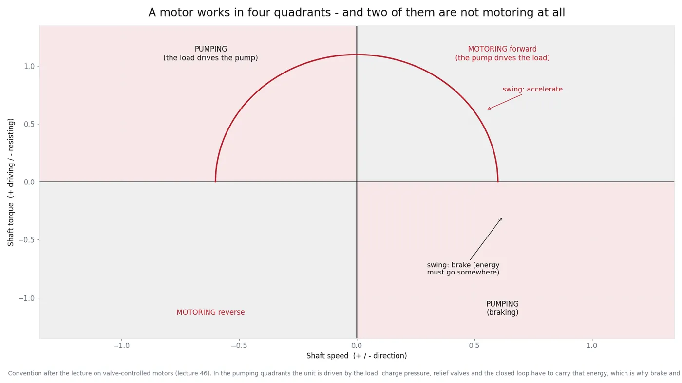
In a closed-circuit drive the hardware that handles those quadrants is the charge pump (which keeps the low-pressure side full so the unit never cavitates), the relief valves on both high-pressure lines (which catch an overrunning load), and the brake valve or counterbalance valve on open circuits. Remove or misadjust any of them and the machine stops braking predictably.
Valve control or pump control
Two families, and the choice is about power. Valve control meters flow: response is fast, but the pressure difference across the metering edge becomes heat. Pump control changes displacement instead: almost no throttling loss, better efficiency, but the unit responds more slowly and needs a servo mechanism to move the swashplate. That is why work implements on an excavator are valve-controlled and travel and swing are pump-controlled - the power level decides.
The case drain is the health check
Every piston motor leaks internally, and that leakage leaves through the case drain. Measure it hot, at working pressure, into a calibrated container for one minute, and compare against the specification. A steady rise over months is the earliest wear indicator you will get; a sudden rise usually comes with contamination or a scored valve plate. Combine it with oil analysis and you have a wear trend that costs almost nothing to maintain.
Field notes for swing and travel complaints
| Complaint | Likely quadrant | Check first |
|---|---|---|
| Swing stops abruptly, machine rocks | Pumping (braking) | Relief and brake valve setting, accumulator if fitted |
| Travel runs away downhill | Overrunning load | Counterbalance or brake valve, charge pressure |
| Both directions slow when hot | Motoring - continuous | Case drain flow, standby pressure, oil temperature |
| Noise and loss of control at speed | Charge circuit | Charge pressure, suction filter, closed-loop oil level |
| One direction weak only | Motoring - one direction | Relief on that side, pilot signal, spool or swashplate control |
Notice that three of the five rows are about the parts that are not the motor. On a machine with a hydrostatic drive, brakes, charge circuits and relief valves fail more often than the rotating group - and they cost a fraction as much.
What to send us
Machine model, motor nameplate, which function and which direction, and the case drain reading hot if you have it. We supply complete travel and swing assemblies (FDNB / FTD, M5X) and the internals - rotating groups, valve plates, seal kits - and the case drain number is usually what decides between a repair kit and a replacement.
Related reading: closed-circuit hydrostatic drives, the three numbers for pump-controlled drives, and travel weak.