Manufacturer reference
Every size the factory publishes, and the parts lists behind them
18 main pump sizes (K3V / K5V / K7V), 4 swing motor classes and the travel drive cross-reference - published by the manufacturer (PNM FK) and reproduced here so you can check a number or a size before you write to us. Where we have a full model page for the unit, the size is linked to it.
Main pumps — size range and series limits
One row per published size. Pressure limits are given per series (rated / peak); the speed column is the maximum continuous speed for that size.
| Size | Series | Displacement | Rated / peak pressure | Max. speed |
|---|---|---|---|---|
| K3V63 | K3V series | 63 cm³ | 34.3 / 39.2 MPa | 2,650 min⁻¹ |
| K3V112 | K3V series | 112 cm³ | 34.3 / 39.2 MPa | 2,360 min⁻¹ |
| K3V140 | K3V series | 140 cm³ | 34.3 / 39.2 MPa | 2,150 min⁻¹ |
| K3V180 | K3V series | 180 cm³ | 34.3 / 39.2 MPa | 1,950 min⁻¹ |
| K3V280 | K3V series | 280 cm³ | 34.3 / 39.2 MPa | 1,600 min⁻¹ |
| K5V80 | K5V series | 80 cm³ | 34.3 / 39.2 MPa | 2,460 min⁻¹ |
| K5V140 | K5V series | 140 cm³ | 34.3 / 39.2 MPa | 2,160 min⁻¹ |
| K5V160 | K5V series | 160 cm³ | 34.3 / 39.2 MPa | 2,000 min⁻¹ |
| K5V200 | K5V series | 200 cm³ | 34.3 / 39.2 MPa | 1,900 min⁻¹ |
| K5V212 | K5V series | 214 cm³ | 34.3 / 39.2 MPa | 2,000 min⁻¹ |
| K7V63 | K7V series | 65 cm³ | 35.0 / 40.0 MPa | 2,650 min⁻¹ |
| K7V125 | K7V series | 130 cm³ | 35.0 / 40.0 MPa | 2,360 min⁻¹ |
| K7V140 | K7V series | 140 cm³ | 35.0 / 40.0 MPa | 2,100 min⁻¹ |
| K7V160 | K7V series | 160 cm³ | 35.0 / 40.0 MPa | 2,100 min⁻¹ |
| K7V180 | K7V series | 180 cm³ | 35.0 / 40.0 MPa | 2,000 min⁻¹ |
| K7V210 | K7V series | 210 cm³ | 35.0 / 40.0 MPa | - |
| K7V240 | K7V series | 242 cm³ | 35.0 / 40.0 MPa | 1,820 min⁻¹ |
| K7V280 | K7V series | 280 cm³ | 35.0 / 40.0 MPa | 1,800 min⁻¹ |
- K7V160 — Manufacturer K3V / K5V / K7V product matrix (PNM FK, pnmfk.co.kr, harvested 2026-09-29); not on the FRANK ordering-code page.
- K7V210 — FRANK catalogue K7V ordering code (pump ordering-code page P5); that page does not publish a speed for this size.
Swing motors
| Model | Displacement | Rated pressure |
|---|---|---|
| M5X80 | 79 cm³ | 33 MPa |
| M5X130 | 129.2 cm³ | 32.4 MPa |
| M5X180 | 180.1 cm³ | 32.4 MPa |
| M5X250 | 250.1 cm³ | 33 MPa |
Travel drives — cross-reference
Left to right: the tonnage class, the FLUTEK unit number, and the equivalent numbers other brands use for the same duty. Machine brands at the end of each row are the applications listed by the manufacturer. Tonnage classes for FDNB08 / FDNB12 / FTD26 / FTD45 / FTD48 follow the FRANK catalogue; the 28-52 t rows follow the manufacturer sheet.
| Class | FLUTEK | NABTESCO | DOOSAN | KAYABA | Machines |
|---|---|---|---|---|---|
| 5-6 t | - | GM06VA | DM06VD | MAG33V-550E | CATERPILLAR, DOOSAN, SANY, SDLG |
| 5-6 t | FDNB08 | TM07VC | - | Kobellco, DOOSAN, VOLVO, HYUNDAI, SANY, SDLG, XCMG, FOTON | |
| 8-10 t | FDNB12 | GM09VL/10VA | TM09/10VD | MAG44VP-800 | Kobellco, Sumitomo, JCB, DOOSAN, VOLVO, HYUNDAI, SANY, SDLG, XCMG, Liugong, FOTON, Lonking |
| 13-16 t | FTD26 | GM18VL/21VA | TM22VC | MAG44VP-800 | Kobellco, Sumitomo, JCB, DOOSAN, VOLVO, HYUNDAI, SANY, SDLG, XCMG, Liugong, FOTON, Lonking, Sunward |
| 18-22 t | FTD45 | GM35VA/VL | TM40VC/VD | MAG85VP-1800 | Kobellco, Sumitomo, JCB, DOOSAN, VOLVO, HYUNDAI, SANY, SDLG, XCMG, Liugong, FOTON, Lonking, Sunward |
| 22-26 t | FTD48 | GM38VL/VB | TM40VC/VD | MAG170VP-3800 | Kobellco, Sumitomo, JCB, DOOSAN, VOLVO, HYUNDAI, SANY, SDLG, XCMG, Liugong, FOTON, Lonking, Sunward |
| 28~34 t | FTD70 | GM60VA | TM60VC/VD | MAG230VP-6000 | Kobellco, Sumitomo, JCB, DOOSAN, VOLVO, HYUNDAI, SANY, SDLG, XCMG, Liugong, FOTON, Lonking, Sunward |
| 36~42 t | FTD80 | GM70VA | TM70VC/VD | - | Kobellco, Sumitomo, JCB, DOOSAN, VOLVO, HYUNDAI, SANY, SDLG, XCMG, Liugong, FOTON, Lonking, Sunward |
| 46~52 t | FTD100 | GM85VA | TM100VD | - | Kobellco, Sumitomo, JCB, DOOSAN, VOLVO, HYUNDAI, SANY, SDLG, XCMG, Liugong, FOTON, Lonking, Sunward |
Travel drives — published figures
Where the FRANK catalogue publishes a figure, that is the figure we quote; the manufacturer sheet figure is kept only for traceability. Speed and torque are listed per speed range (Speed-1 / Speed-2) because these travel devices shift between two displacements. The last three sizes are not in the FRANK catalogue, so their row carries the manufacturer sheet figures.
| Model | Application | Figures from | Max. flow (L/min) | Relief valve set pressure (MPa) | Gear ratio | Displacement S1 (cm³) | Displacement S2 (cm³) | Output speed S1 (min¹) | Output speed S2 (min¹) | Output torque S1 (N·m) | Output torque S2 (N·m) |
|---|---|---|---|---|---|---|---|---|---|---|---|
| FDNB08 | 5-6 t | FRANK catalogue | 57.8 | 21.6 | 53.706 | 43.1 (max. 54.9) | 22.3 | 25.9 | 50.1 | 7,946.7 | 4,111.7 |
| FDNB12 | 8-10 t | FRANK catalogue | 55 | 28 | 53.706 | 45 (max. 54.9) | 22.9 | 22.8 | 44.7 | 10,773 | 5,484 |
| FTD26 | 13-16 t | FRANK catalogue | 138.6 | 34.3 | 49.569 | 92.5 (max. 95.34) | 50.6 | 30.2 | 55.2 (max. 60) | 25,056 (max. 25,800) | - |
| FTD45 | 18-22 t | FRANK catalogue | 252 | 34.3 | 45.255 | 180.1 | - | - | 58.8 (max.) | 44,520 (max.) | - |
| FTD48 | 22-26 t | FRANK catalogue | 252 | 34.3 | 48.939 | 180.1 | - | - | 54.2 (max.) | 47,580 (max.) | - |
| FTD70 | 28~34 t | maker sheet | - | - | - | - | - | - | 50 | 70,000 (7,140) | - |
| FTD80 | 36~42 t | maker sheet | - | - | - | - | - | - | 43.5 | 79,570 (8,110) | - |
| FTD100 | 46~52 t | maker sheet | - | - | - | - | - | - | 36 | 100,100 (10,210) | - |
Travel drives — brake, pressure and the manufacturer sheet
Brake torque and maximum pressure are not published in the FRANK catalogue; they come from the manufacturer travel device sheet, with the output speed printed there. Where the two sources differ, the FRANK figure in the table above is the one we quote.
| Model | Max. pressure MPa (kgf/cm²) | Brake torque N·m (kgf·m) | Max. output speed on the sheet (min¹) |
|---|---|---|---|
| FDNB08 | 34.3 (350) | 137 (14) | 60 |
| FDNB12 | 34.3 (350) | 137 (14) | 60 |
| FTD26 | 34.3 (350) | 265 (27) | 60 |
| FTD45 | 34.3 (350) | 621 (63.3) | 58.5 |
| FTD48 | 34.3 (350) | 621 (63.3) | 54.2 |
| FTD70 | 35.8 (365) | 1,128 (115) | 50 |
| FTD80 | 35.8 (365) | 1,128 (115) | 43.5 |
| FTD100 | 35.8 (365) | 1,128 (115) | 36 |
Travel drives — flange and outline dimensions
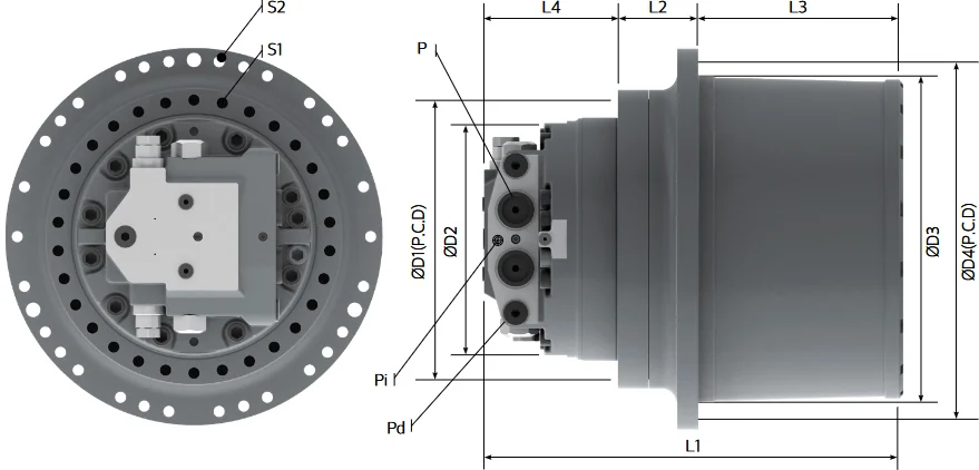
Unit: mm, from the manufacturer sheet — the FRANK catalogue prints the structure drawing but not the dimension table. D1 and D4 are the pitch circles, D2 and D3 the centring diameters, L1 to L4 the axial lengths. P, Pi and Pd are the main, pilot and drain ports; S1 and S2 are the bolt patterns. Measure the flange and the sprocket bolt circle on your machine before ordering.
| Model | D1 | D2 | D3 | D4 | L1 | L2 | L3 | L4 | P | Pi | Pd | S1 | S2 |
|---|---|---|---|---|---|---|---|---|---|---|---|---|---|
| FDNB08 | 244 | 210 | 250 | 282 | 336.5 | 68 | 147 | 121.5 | PF 1/2 | PF 1/4 | PF 3/8 | 12-M14 | 12-M14 |
| FDNB12 | 250 | 210 | 265 | 300 | 355.5 | 80 | 154 | 121.5 | PF 1/2 | PF 1/4 | PF 3/8 | 12-M14 | 12-M14 |
| FTD26 | 280 | 246 | 324 | 364 | 412.3 | 99.5 | 192 | 120.8 | PF 3/4 | PF 1/4 | PF 1/2 | 20-M16 | 15-M16 |
| FTD45 | 340 | 300 | 402 | 440 | 515.5 | 98.5 | 252 | 165 | PF1 / SAE 1" | PF 1/4 | PF 1/2 | 30-M16 | 30-M16 |
| FTD48 | 340 | 300 | 402 | 440 | 515.5 | 98.5 | 252 | 165 | PF1 / SAE 1" | PF 1/4 | PF 1/2 | 30-M16 | 30-M16 |
| FTD70 | 425 | 380 | 450 | 490 | 575 | 112 | 290 | 173 | SAE 1" | PF 1/4 | PF 1/2 | 26-M20 | 24-M20 |
| FTD80 | 425 | 380 | 450 | 490 | 575 | 112 | 290 | 173 | SAE 1" | PF 1/4 | PF 1/2 | 26-M20 | 24-M20 |
| FTD100 | 460 | 420 | 510 | 550 | 634 | 130 | 331 | 173 | SAE 1 1/4" | PF 1/4 | PF 1/2 | 24-M24 | 32-M20 |
Travel drive model code
Read the unit code left to right — for example FTD 45 V 45 180/102 35 01. The output torque code and the reduction ratio are the two positions to quote when you ask for a replacement.
| Position | Field | Example |
|---|---|---|
| 1 | Model | FTD |
| 2 | Output Torque | 45 |
| 3 | Speed Shifting | V |
| 4 | Reduction Ratio | 45 |
| 5 | Displacement | 180/102 |
| 6 | System Pressure | 35 |
| 7 | Revision | 01 |
Control codes
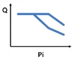
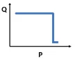
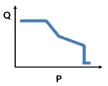
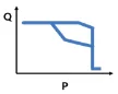
The letter or digit after the displacement in a model code tells you how the pump is controlled. Power control codes and flow control codes are separate positions in the code, so two units with the same displacement and a different code behave differently in the operator's hands — which is why we confirm it from the nameplate.
Power control codes
| Code | Control type | Source |
|---|---|---|
| 0 | free power setting control | Catalogue P.5 |
| 1 | constant power control | Catalogue P.5 |
| 2 | total power control | Catalogue P.5 |
| 4 | pressure cut-off control | Catalogue P.5 |
| 5 | constant power + pressure cut-off control | Catalogue P.5 |
| 6 | total power + pressure cut-off control | Catalogue P.5 |
| 9 | total power + power shift control (power reduction only) | Catalogue P.5 |
| H | total power + power shift control (increase and decrease power) | Catalogue P.5 |
Flow control codes
| Code | Control type | Source |
|---|---|---|
| 0 | no flow control | Catalogue P.5 |
| N | negative flow control | Catalogue P.5 |
| P | positive flow control | Catalogue P.5 |
| M | manual flow control | Catalogue P.5 |
| E | electric flow control | Catalogue P.5 |
| C | negative flow control (2-stage max. flow control) | Catalogue P.5 |
| D | positive flow control (with flow cut-off control) | Catalogue P.5 |
| T | electric proportional flow control (with electric hydraulic switch valve) | Catalogue P.5 |
| L | load sensing control | Maker sheet |
No control curve is published for 0 (power: free power setting control), H (power: total power + power shift control (increase and decrease power)), 0 (flow: no flow control), D (flow: positive flow control (with flow cut-off control)), T (flow: electric proportional flow control (with electric hydraulic switch valve)); those codes are listed above without a diagram.
Engineering drawings
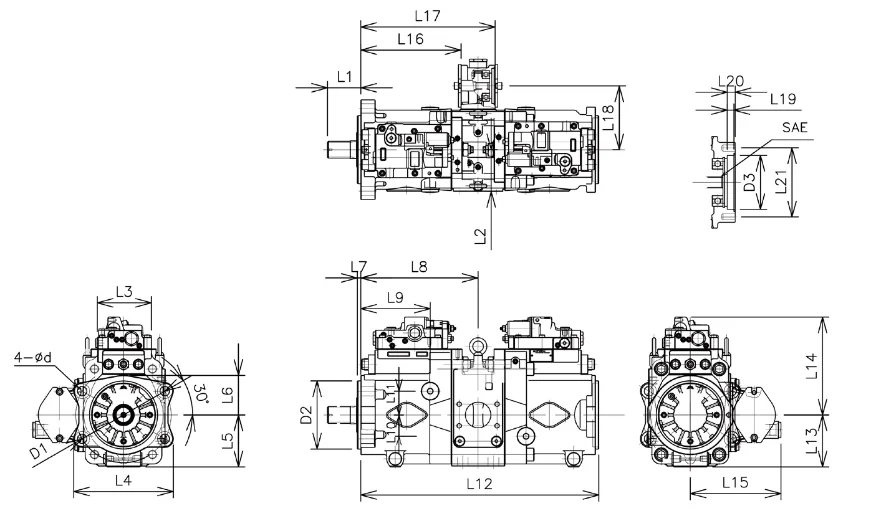
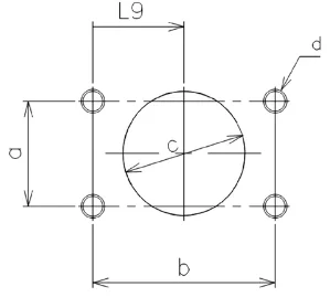
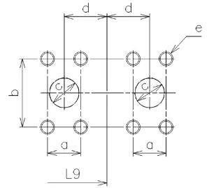
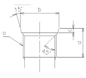
Outline dimensions, port positions and control diagrams as the manufacturer publishes them. Use them to check the mounting and the port layout before you order; we confirm the exact variant on your nameplate.

Control diagrams
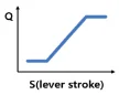
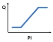
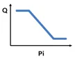
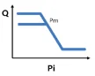
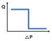
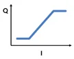
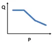
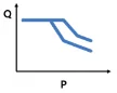
One diagram per published control curve, including the constant-power-plus-pressure-cut-off (5) and total-power-plus-pressure-cut-off (6) curves; codes with no published curve are listed in the code tables above only.
Parts lists
Main pump parts list
54 published lines: drawing position, part name, part number and quantity per set for the K3V / K5V / K7V pump family.
Swing motor parts list
40 published lines for the M5X swing motor and swing device family, same columns.
Parts tables from our FRANK sample catalogue
Drawing position, part number and quantity per set, page by page, from our own 65-page FRANK English sample catalogue. Part names are matched to the catalogue and to the factory list by position; unmatched names are left as name to be confirmed instead of copied from the PDF text layer.
Archived number references
Our reference index of archived parts-number pages by brand, for numbers that are not in either published list.