
The torque motor at the front
Every electrically controlled valve starts with an electro-mechanical converter: an electrical command in, a small mechanical displacement out. In a torque motor that displacement is angular; in a linear force motor it is a straight push. Either way the requirements are the same - the output must be proportional to the signal, it must not wander with temperature or pressure, and it should waste as little energy as possible in the magnetic circuit and the coil.
That is why a marginal coil or a contaminated pilot stage makes a machine behave "electrically" even though the fault is hydraulic. The first stage is tiny, and tiny things are sensitive.
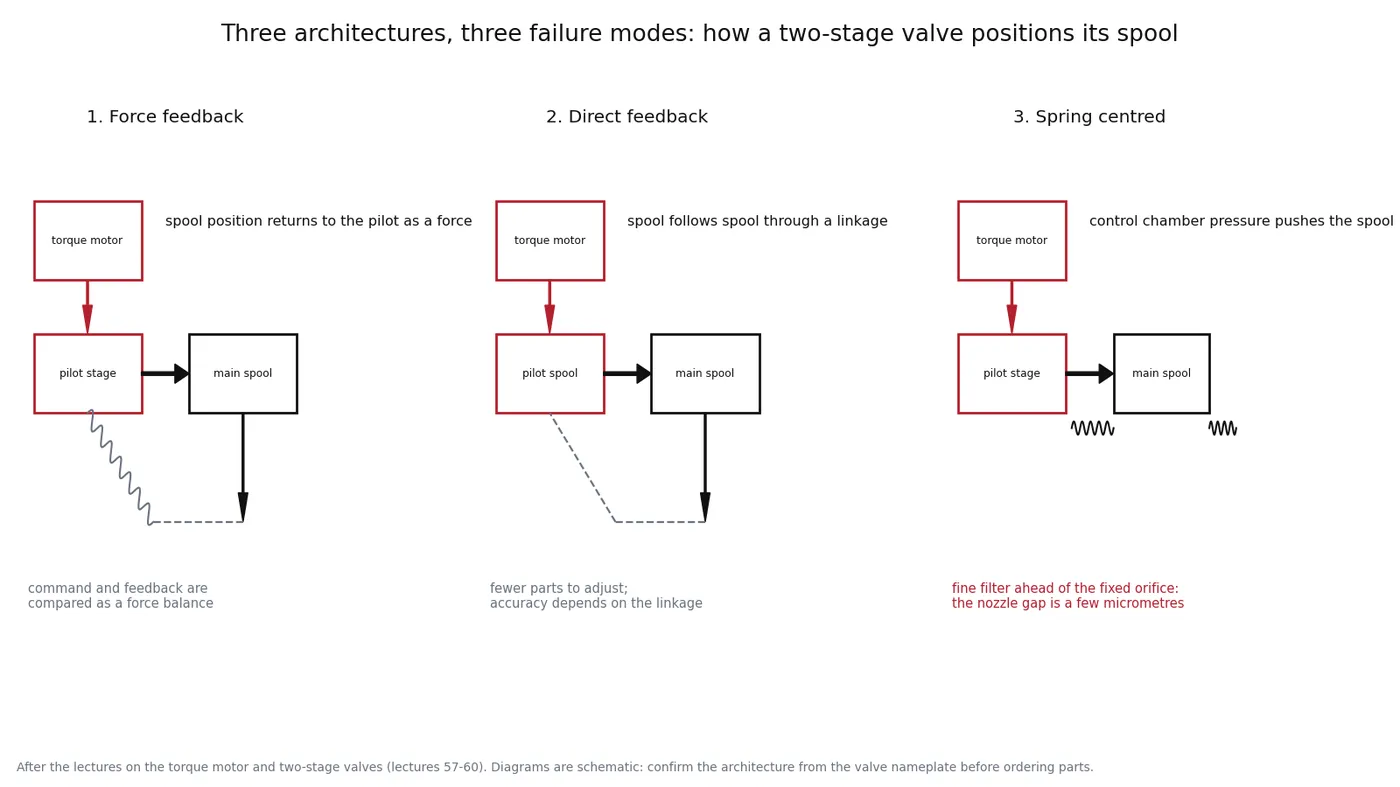
1. Force feedback - the classic servo valve
A pilot stage (nozzle-flapper or jet pipe) produces a small pressure difference that pushes the main spool. A feedback spring connects the main spool back to the pilot stage, so spool movement returns as a force. The valve settles where the command force and the feedback force balance.
It is accurate and repeatable, and it is what most people mean by "servo valve". Its weakness is the pilot stage: gaps of a few micrometres, a feedback spring that can be damaged, and a nozzle that a single particle can block.
2. Direct feedback - spool follows spool
Here the torque motor drives the pilot spool directly, and the main spool follows it mechanically. There is no feedback spring to adjust and fewer parts to wear, so the valve is simple and fast. The price is that accuracy depends on the mechanical follow-up: clearances, wear in the linkage and contamination all show up in the output.
3. Spring centred - the pressure balance
A fixed orifice feeds a control chamber; a flapper varies the escape path from that chamber to return. The pressure in the chamber moves the main spool, and centring springs bring it back when the command disappears. The important detail for a machine owner is upstream of the valve: this design places a fine filter before the fixed orifice, because the nozzle and flapper gap is only a few micrometres. If that filter is missing or bypassed, the valve works for a while and then becomes intermittent.
What this means when a valve misbehaves
| Architecture | Typical failure | First check |
|---|---|---|
| Force feedback | Slow or drifting response; spool settles off centre | Pilot filter and nozzle, then the feedback spring and its adjustment |
| Direct feedback | Jumpy response; output not proportional to command | Coil current and resistance, then wear in the pilot spool and linkage |
| Spring centred | Intermittent operation: works, then stops | The filter ahead of the fixed orifice, then the centring springs |
| Any of them with a proportional solenoid | Late, stepped or dead response | Current at the coil, connector condition, calibration, pilot pressure |
Before you replace a valve
- Measure the coil: resistance cold and hot, and the current the controller actually commands.
- Check the pilot supply: pressure, and - more often than people expect - cleanliness.
- Read the fault log and the calibration: a controller with the wrong configuration mimics a bad valve perfectly.
- Change the filter and flush before condemning anything with a nozzle in it.
Most of the two-stage valves we see condemned were fixed by numbers 3 and 4. When a replacement really is needed, the nameplate identifies the architecture and the flow rating, and we confirm the mating part against the pump or block it sits on.
Related reading: pilot stages explained, cleanliness targets by system type, and proportional solenoid response.